Bus tab
The Bus tab is the first tab in the EtherCAT Bus Editor and the place where you discover what is physically attached to your segment. Open it by clicking the bus node (e.g. eth) in the project tree.
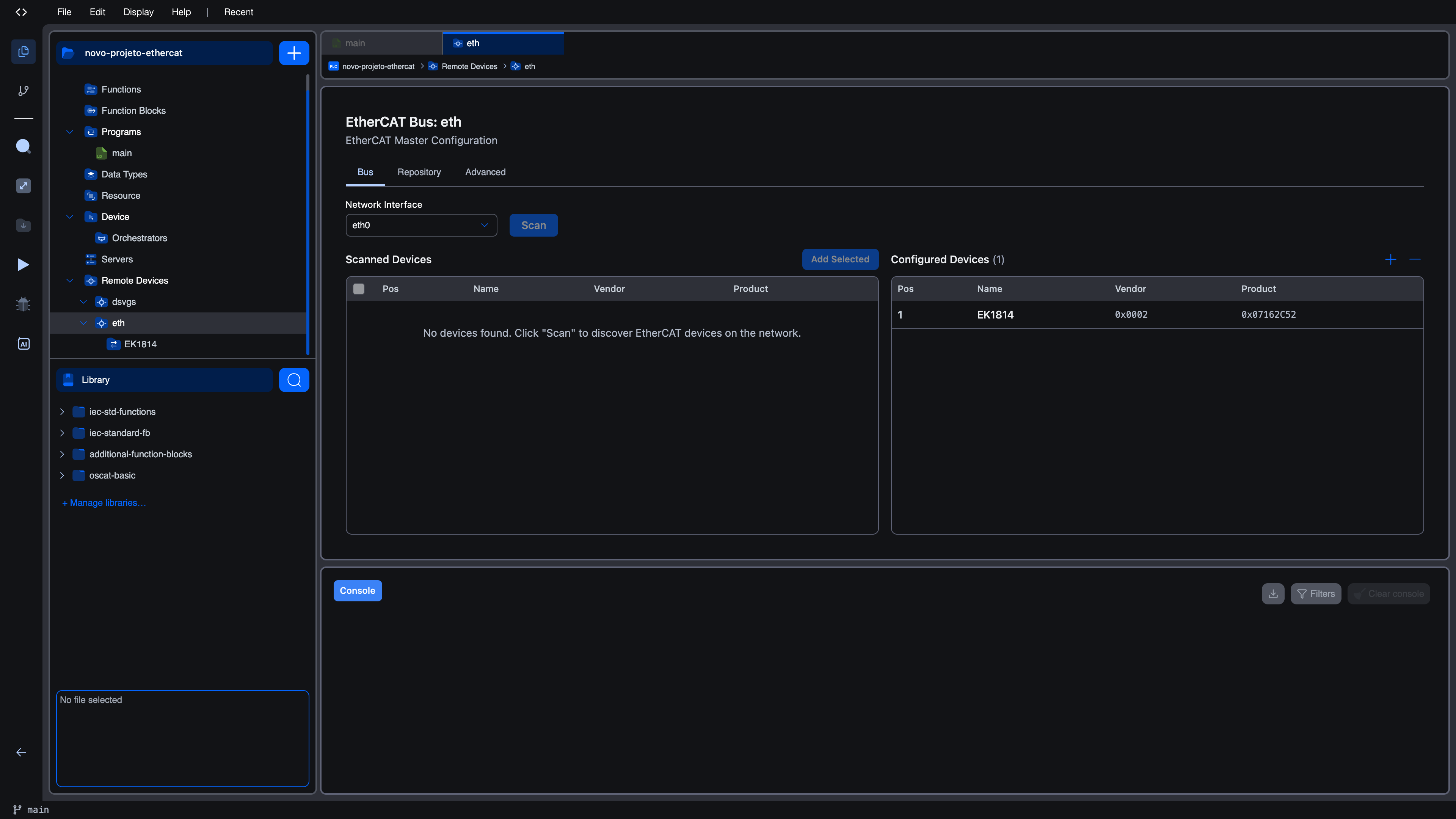
The header at the top of the editor reads EtherCAT Bus: <name> followed by the subtitle EtherCAT Master Configuration. The three tabs underneath are Bus, Repository, and Advanced.
What you see at a glance
The Bus tab is laid out in two side-by-side panels:
| Panel | Purpose |
|---|---|
| Left. Scanned Devices | Devices discovered on the wire after the most recent Scan. Each one has a checkbox; selecting and clicking Add Selected moves the device into the right panel. |
| Right. Configured Devices | The slaves that are part of your project. Each row becomes a child node in the project tree. The ➕ and ➖ icons at the top right add devices manually from the repository or remove a selected one. |
Above both panels sits the Network Interface dropdown and the Scan button.
Selecting a network interface
Click the Network Interface dropdown to see the list of NICs the runtime reports. Each option shows the kernel device name (for example enp4s0, eth0, enx00e04c680001) and, when available, a friendly description.
The dropdown is also editable: if the interface you want is not yet in the list. For example because you just added a USB NIC and the runtime has not refreshed. You can type its name and press Enter, and the editor will use that value. The choice is persisted in the bus configuration; opening the project later restores the same interface.
Reminder. Pick a NIC that is dedicated to EtherCAT. Sharing the interface with management traffic causes intermittent working-counter errors. See Prerequisites for the rules.
Running a scan
Once a NIC is selected, the Scan button becomes active only when:
- The runtime is connected (the editor's runtime indicator reads "connected"), and
- The EtherCAT discovery service reports as available on that runtime.
If the runtime is not connected, the Scan button stays disabled. If the runtime is connected but the service is not available, a yellow banner reads EtherCAT Discovery Service Not Available along with a short explanation from the runtime. See Troubleshooting.
When you click Scan, the master sends a discovery sweep on the chosen NIC and waits up to a few seconds for slaves to respond. The button text changes to Scanning… while it runs. When the scan finishes, you see a Completed in <N>ms indicator next to the button along with a short message from the runtime.
If no slaves respond, the table on the left shows No devices found. Click "Scan" to discover EtherCAT devices on the network.
Reading the discovered-device table
Each scanned device is one row with these columns:
| Column | Meaning |
|---|---|
| Checkbox | Select this device for Add Selected. |
| Pos | Position on the daisy-chain (1, 2, 3, … starting from the master). |
| Name | Friendly device name, taken from the matched ESI XML when available. If no match was found, you also see a small No XML badge. See below. |
| Vendor | The 16-bit vendor ID reported by the slave, in hex (e.g. 0x0002 for Beckhoff). |
| Product | The 32-bit product code (e.g. 0x044C2C52). |
Rows with a No XML badge mean the master found a slave on the wire but no ESI XML in your project's repository describes that vendor/product/revision combination. You can still tick the checkbox, but adding it will fail with a modal explaining how to import the XML. See "Missing ESI XML" below.
Adding scanned devices to the configuration
Tick the checkboxes next to the slaves you want to control, then click Add Selected. The button label changes to Add Selected (N) while at least one row is selected. For each successfully matched slave, the editor:
- Creates a configured device with default per-slave settings. See Configuration for the defaults.
- Loads channel definitions from the ESI XML and pre-assigns IEC located variables (
%IX,%QX,%IW,%QW) so the device is immediately mappable. - Adds a child node under the bus in the project tree.
The successfully-added rows have their checkboxes cleared. Devices that failed because of a missing ESI stay selected so you can see which ones still need attention.
Missing ESI XML
If you select a row marked No XML and click Add Selected, a modal titled Missing ESI XML for some devices appears. It lists the affected slaves with their position, name, vendor, and product code, and offers a short "How to fix" recipe:
- Download the ESI XML for each device from the manufacturer's website.
- Open the Repository tab and import the XML files there.
- Re-run the scan and click Add Selected again.
The modal has two buttons: Go to Repository (jumps directly to the Repository tab) and OK (closes the modal so you can fix the problem later).
Building the configuration without a scan
If the segment is not yet wired up, or you want to plan a project before hardware is on the bench, you can build the configuration entirely from the repository:
-
Switch to the Repository tab and upload the ESI files for the devices you intend to use.
-
Come back to the Bus tab.
-
Click the
+icon at the top right of the Configured Devices panel. The Add Device from Repository modal opens.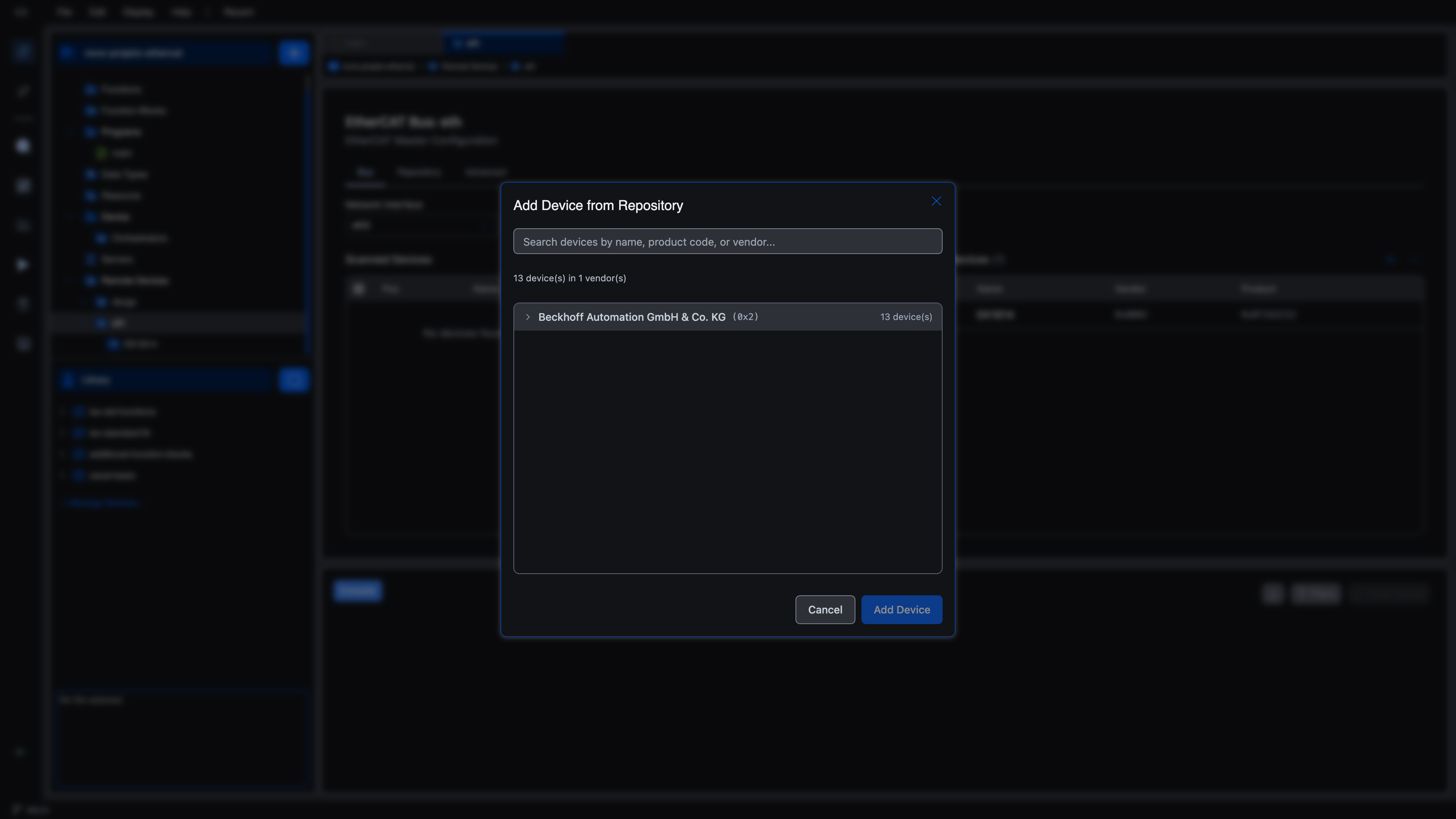
-
Use the search box at the top of the modal (
Search devices by name, product code, or vendor…) or expand a vendor row to browse.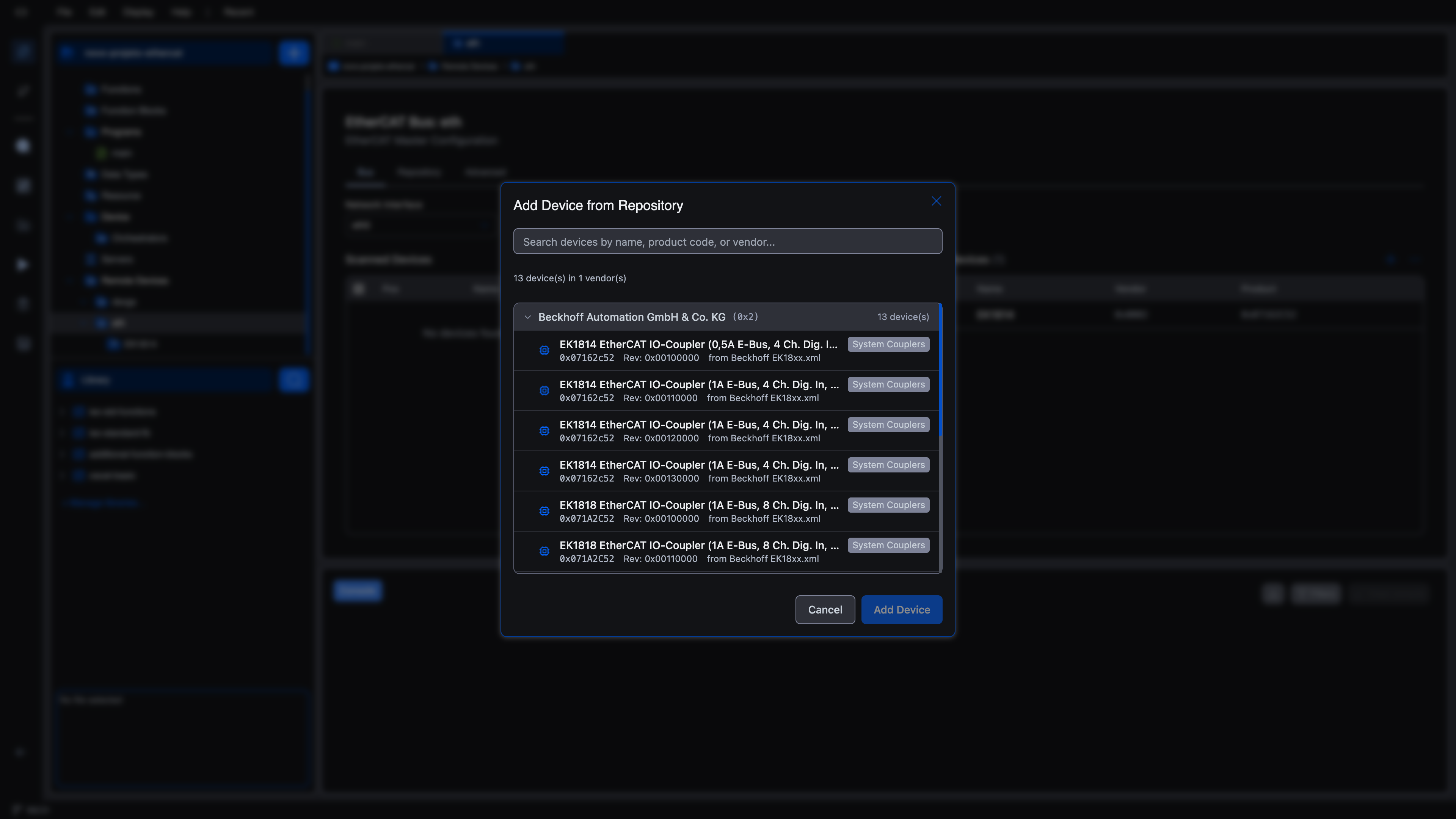
Each device row shows the name, product code, revision, and source ESI file.
-
Select a device and click Add Device. The slave appears under your bus in the project tree, and in the Configured Devices panel, with a position assigned automatically (one greater than the highest existing position).
You can mix the two approaches. Start with what you have, fill in the rest after a scan. Without losing work.
Removing a configured device
In the Configured Devices panel, click a row to select it (the row is highlighted). Click the ➖ icon to remove it. Removing a slave deletes its channel mappings and its child node, but leaves the underlying ESI in the repository so you can re-add the device later.
What's next?
- Repository to manage ESI files
- Advanced to set the master cycle time and watchdog
- Channel Mappings to wire each slave's I/O onto your IEC variables
On This Page