Data Blocks
A Siemens Data Block (DB) is a chunk of structured memory that S7 clients address as DB<n>. In an S7-300 program a DB is created in the engineering tool and filled with named variables. In Autonomy Edge, a Data Block is a view onto an existing PLC buffer. You decide what kind of data it exposes (Boolean Output, Word Memory, Long Word Input, …), how big the view is, and where in the buffer it starts.
External clients connect, read or write DB<n>.DBX<byte>.<bit> (for bit access) or DB<n>.DBW<byte> (for word access), and your PLC program sees the changes on its next scan.
The Data Blocks accordion header includes a counter such as Data Blocks (1/64) showing how many DBs are configured against the project's hard limit of 64.
Mapping Type, the 14 buffer types
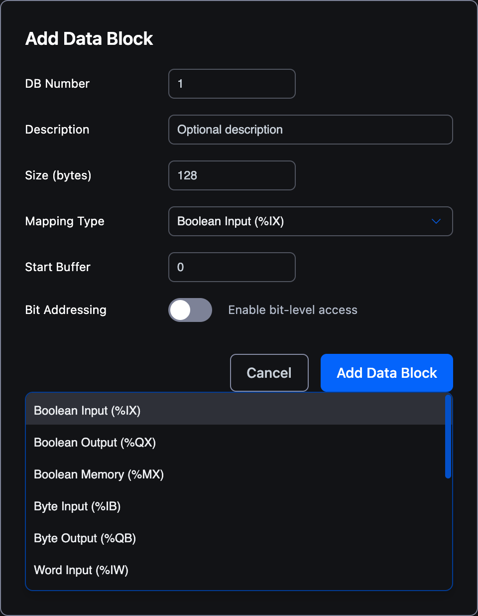
The dropdown lists all 14 PLC-memory areas a DB can expose:
| Mapping Type | IEC | Bits/Bytes |
|---|---|---|
| Boolean Input | %IX | 1 bit |
| Boolean Output | %QX | 1 bit |
| Boolean Memory | %MX | 1 bit |
| Byte Input | %IB | 8 bits |
| Byte Output | %QB | 8 bits |
| Word Input | %IW | 16 bits |
| Word Output | %QW | 16 bits |
| Word Memory | %MW | 16 bits |
| DWord Input | %ID | 32 bits |
| DWord Output | %QD | 32 bits |
| DWord Memory | %MD | 32 bits |
| LWord Input | %IL | 64 bits |
| LWord Output | %QL | 64 bits |
| LWord Memory | %ML | 64 bits |
Note this is a strictly broader set than Modbus exposes. Modbus only surfaces a subset (bits and 16-bit registers). If you need 32-bit or 64-bit values mapped directly without manual word-splitting, S7Comm is the more natural fit.
Adding a Data Block
- Expand the Data Blocks accordion.
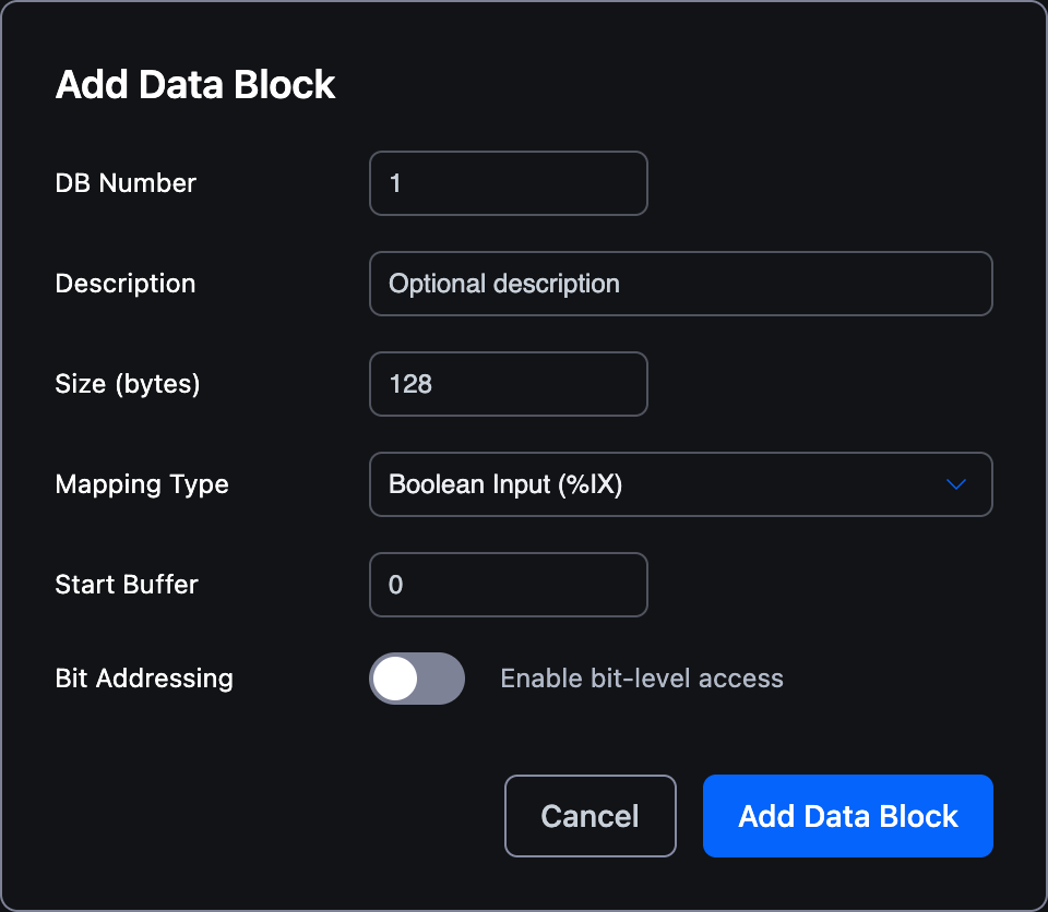
- Click + Add Data Block. A modal opens.
- Fill in DB Number, Description, Size, Mapping Type, and Start Buffer (and Bit Addressing for boolean mappings. See below).
- Click Add Data Block in the modal to confirm.
The new DB appears in a table inside the accordion with columns DB, Description, Size, Type, and Actions (edit / delete).
When the project has no DBs yet, the empty-state message reads:
No data blocks configured. Add a data block to expose PLC data to S7 clients.
When 64 DBs are already configured, the + Add Data Block button is disabled.
Modal Fields
| Field | Type | Default | Range | Description |
|---|---|---|---|---|
| DB Number | Number | 1 | 1 -- 65535 | The Siemens DB index visible to clients (DB1, DB2, …). Must be unique within this server. |
| Description | Text | empty | up to 128 characters | Optional human-readable note. Placeholder text reads Optional description. |
| Size (bytes) | Number | 128 | 1 -- 65536 | Total size of the DB exposed to clients. |
| Mapping Type | Dropdown | Boolean Input (%IX) | see catalog below | Which OpenPLC buffer the DB is a window into. |
| Start Buffer | Number | 0 | 0 -- 1023 | Offset into the chosen buffer where this DB begins. |
| Bit Addressing | Toggle | Off | -- | Only shown for bool_* mapping types. When on, the DB exposes individual bits (DB<n>.DBX<byte>.<bit>) rather than packed bytes. Helper text: Enable bit-level access. |
Validation
The modal blocks the save action when:
- DB Number is out of range →
DB Number must be between 1 and 65535 - DB Number already exists →
DB<n> already exists(e.g.DB1 already exists) - Size is out of range →
Size must be between 1 and 65536 bytes - Start Buffer is out of range →
Start buffer must be between 0 and 1023
Errors appear in red below the form fields. Fix the offending value and the modal will accept the entry.
Mapping Type Catalog
The Mapping Type dropdown lists 14 buffer areas grouped by data width. The labels below match the editor verbatim.
| Label | Element Width | Direction | IEC Prefix | Use For |
|---|---|---|---|---|
| Boolean Input (%IX) | 1 bit | Read from device | %IX | Digital inputs |
| Boolean Output (%QX) | 1 bit | Write to device | %QX | Digital outputs |
| Boolean Memory (%MX) | 1 bit | Internal | %MX | Internal markers |
| Byte Input (%IB) | 1 byte | Read from device | %IB | Byte inputs |
| Byte Output (%QB) | 1 byte | Write to device | %QB | Byte outputs |
| Word Input (%IW) | 2 bytes | Read from device | %IW | Word inputs |
| Word Output (%QW) | 2 bytes | Write to device | %QW | Word outputs |
| Word Memory (%MW) | 2 bytes | Internal | %MW | Word memory |
| Double Word Input (%ID) | 4 bytes | Read from device | %ID | DWord inputs |
| Double Word Output (%QD) | 4 bytes | Write to device | %QD | DWord outputs |
| Double Word Memory (%MD) | 4 bytes | Internal | %MD | DWord memory |
| Long Word Input (%IL) | 8 bytes | Read from device | %IL | LWord inputs |
| Long Word Output (%QL) | 8 bytes | Write to device | %QL | LWord outputs |
| Long Word Memory (%ML) | 8 bytes | Internal | %ML | LWord memory |
The three columns to remember:
Input(%I): Data flowing into the PLC (sensors, field inputs). Clients reading these values see whatever the PLC has acquired most recently.Output(%Q): Data flowing out of the PLC (relays, drives, indicator lights). Clients can both read and write; writes update the PLC outputs on the next scan.Memory(%M): Internal state, neither directly tied to a sensor nor an actuator. Clients reading or writing memory see and change the PLC's working variables.
Sizing Guidance
The Size (bytes) value is the size of the DB window the client sees, expressed in bytes regardless of the chosen mapping type. The number of addressable elements depends on the element width:
| Mapping Width | Elements in Size (bytes) |
|---|---|
1 bit (bool_*) | Size * 8 individual bits when Bit Addressing is enabled |
1 byte (byte_*) | Size bytes |
2 bytes (int_*) | Size / 2 words |
4 bytes (dint_*) | Size / 4 double words |
8 bytes (lint_*) | Size / 8 long words |
For example:
- A Boolean Output (%QX) DB of
Size = 1byte with Bit Addressing enabled exposes 8 individual coils (DBX0.0throughDBX0.7). - A Word Memory (%MW) DB of
Size = 64bytes exposes 32 sequential 16-bit words. - A Long Word Input (%IL) DB of
Size = 80bytes exposes 10 sequential 64-bit values.
Pick the smallest size that covers the variables you actually need to expose. Smaller DBs are quicker to transfer over the network and easier for HMI screens to refresh.
Editing and Deleting
Each row in the Data Blocks table has two action icons in its rightmost column:
- The pencil icon opens the modal pre-filled with the DB's current values for editing. You cannot rename a DB to a number that already exists; the same
DB<n> already existsvalidation applies (the DB you are editing is exempt). - The trash icon removes the DB. There is no separate confirmation step. Clicking the icon deletes the entry immediately.
Both actions mark the project as modified, so you can still revert by closing the project without saving.
What's Next?
- PLC Identity: Customise what HMIs see when they ask for the CPU model
- Example: Walk through configuring DB1 against the blink project
- S7Comm Server Overview: Return to the protocol overview
On This Page