Quick Start Guide
This guide walks you through creating your first automation project on the Autonomy Edge platform, from setting up your environment to deploying a simple blinking output program to a virtual PLC.
Understanding Autonomy Edge
Autonomy Edge is a cloud-based platform for industrial automation that brings modern software development practices to PLC programming. Instead of requiring specialized hardware and proprietary software installations, Autonomy Edge lets you develop, deploy, and manage automation programs entirely from your web browser.
Why Autonomy Edge?
Traditional PLC development requires expensive hardware, proprietary software licenses, and physical access to devices. Autonomy Edge removes these barriers by providing:
- Browser-Based Development: Write PLC programs using industry-standard IEC 61131-3 languages without installing any software
- Virtual PLCs: Deploy automation logic to physical devices (PLCs, PACs, Industrial PCs, Servers) running in containerized runtime instances in real-time
- Remote Management: Deploy programs and monitor devices from anywhere with an internet connection (internet is only required for management, not for running control logic)
- Cloud Collaboration: Share projects with team members and maintain version history automatically
Platform Architecture
The Autonomy Edge ecosystem consists of four key components that work together:
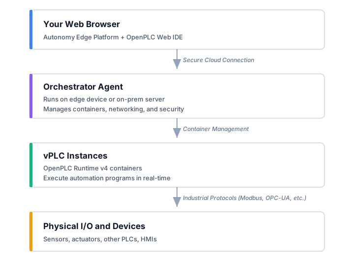
Autonomy Edge Platform: The cloud-based web application where you manage projects, users, and vPLCs. It includes the browser-based OpenPLC Editor IDE for writing automation programs.
Device: Your edge machine (a linux-based PLC, PAC, industrial PC, or on-prem server), registered with the platform. The Device Agent runs on it, manages your vPLC instances, maintains a secure connection to the cloud, and handles container orchestration, networking, and system monitoring.
vPLC (Virtual PLC): A containerized instance of OpenPLC Runtime v4 that executes your automation programs. Each vPLC runs independently and can communicate with physical devices through industrial protocols like Modbus, EtherCAT, or EtherNet/IP.
Physical I/O and Devices: The sensors, actuators, remote I/O modules, HMIs, and other industrial equipment that connect to your vPLCs through industrial protocols like Modbus TCP/IP, Modbus RTU, EtherCAT, or EtherNet/IP.
IEC 61131-3 Programming
Autonomy Edge supports all five standard IEC 61131-3 programming languages:
| Language | Type | Best For |
|---|---|---|
| Structured Text (ST) | Textual | Complex algorithms, calculations, data processing |
| Ladder Diagram (LD) | Graphical | Discrete logic, familiar to electricians |
| Function Block Diagram (FBD) | Graphical | Process control, signal flow visualization |
| Instruction List (IL) | Textual | Low-level control, legacy system migration |
| Sequential Function Chart (SFC) | Graphical | State machines, sequential processes |
Additionally, you can extend functionality with Python and C++ function blocks for advanced use cases like machine learning integration or custom protocol handlers.
What You'll Build
In this guide, you'll create a complete automation workflow from scratch:
- Set up infrastructure: Install the Device Agent on your device and provision a vPLC instance
- Develop a program: Write a "Hello World" blinking output program in Structured Text
- Configure communication: Set up Modbus TCP/IP to expose your outputs to external devices
- Deploy and run: Compile and upload your program to the vPLC
Prerequisites
- Autonomy Edge account: Sign up at edge.autonomylogic.com if you haven't already
- Modern web browser: Chrome, Firefox, or Safari recommended for the best experience
- Linux device: Any Linux-based device where you have SSH or terminal access (PLC, PAC, Industrial PC, Server, Raspberry Pi, etc.)
- Modbus slave device: A remote I/O module or device with at least one digital output that supports Modbus TCP/IP. This will receive the blinking output signal from your program.
Step 1: Set Up a Device
A Device is your edge machine. The Device Agent runs on it, manages your vPLCs, and maintains a secure connection to the Autonomy Edge cloud.
1.1 Start the New Device Wizard
- Log in to the Autonomy Edge platform at edge.autonomylogic.com
- Navigate to Devices in the left sidebar
- Click the Add Device button
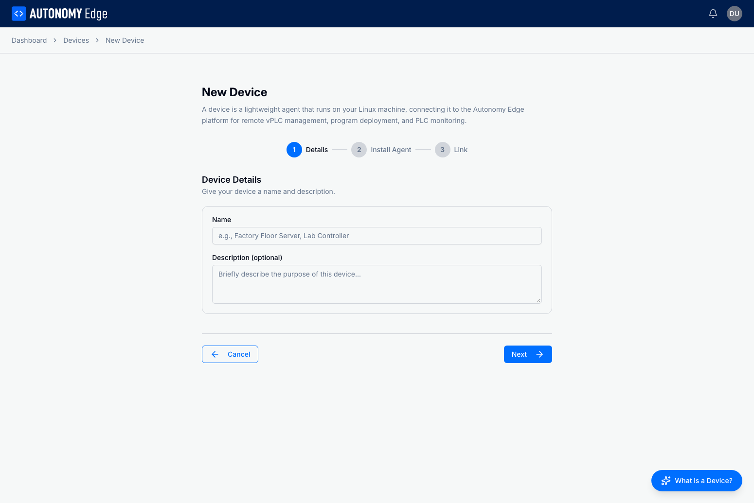
1.2 Enter Device Details
- Enter a name for your Device (e.g., "QuickStartDevice")
- Optionally add a description
- Click Next to proceed to the Install step
1.3 Install the Agent on Your Device
The wizard provides a curl command to install the Device Agent on your Linux device.
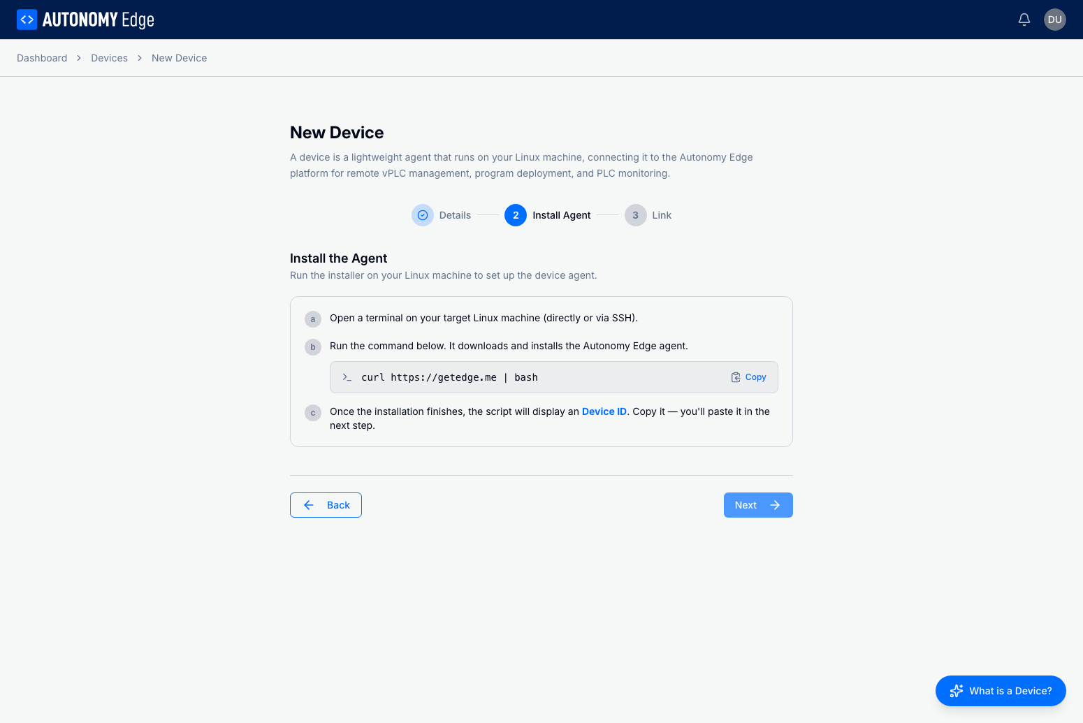
- Click Copy to copy the installation command
- Open a terminal on your Linux device (via SSH or directly)
- Paste and run the command:
curl https://getedge.me | bash - Follow the on-screen prompts to complete the installation
- When the installation completes, the agent will display a Device ID
1.4 Link the Device
After installation, the agent generates an ID that you need to enter in the platform.
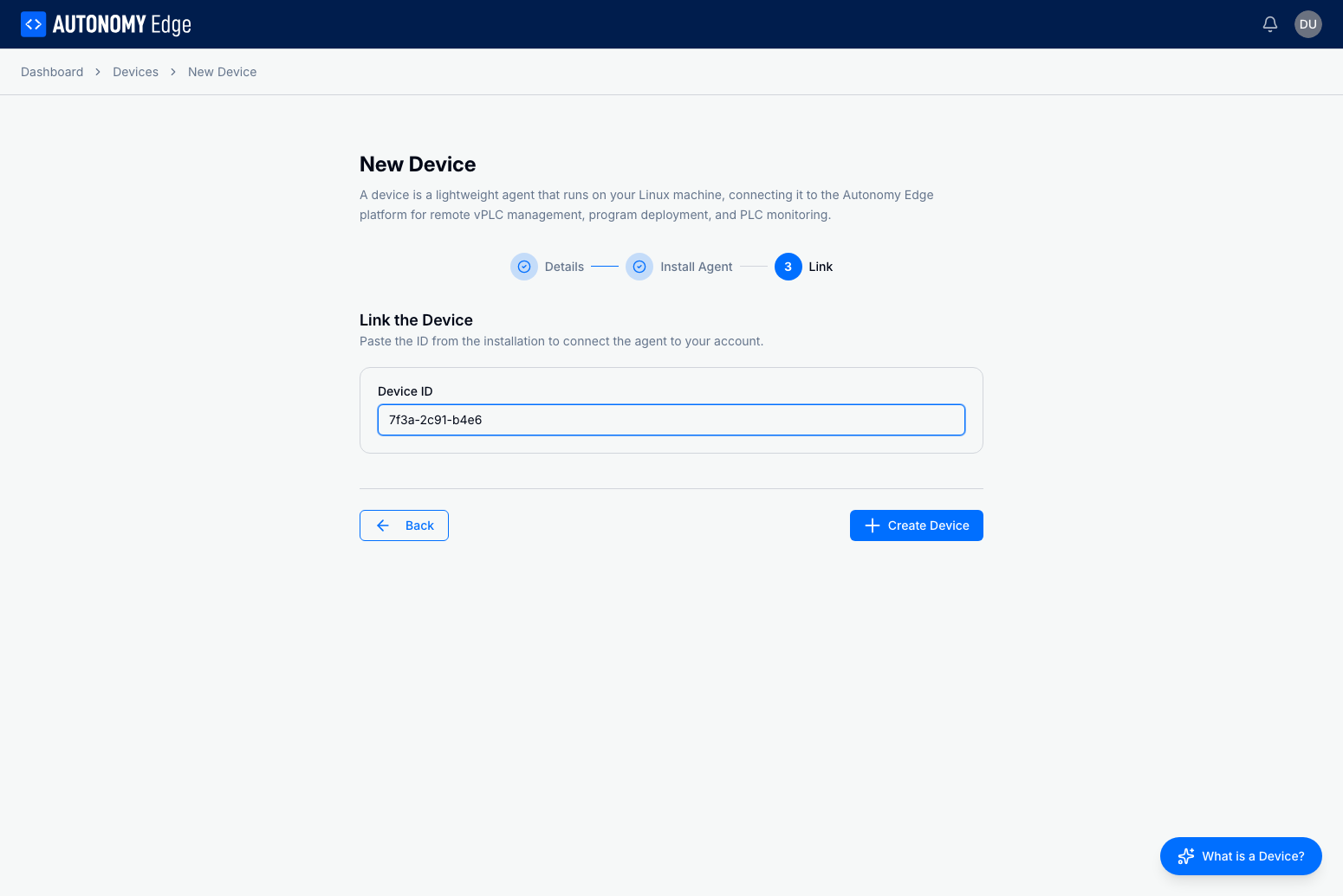
- Copy the Device ID from your terminal
- Paste it into the Device ID field
- Click Create Device
Note: The Device ID expires after 5 minutes. If it expires, run the installation command again to generate a new ID.
Once linked, your Device will appear in the list with its connection status.
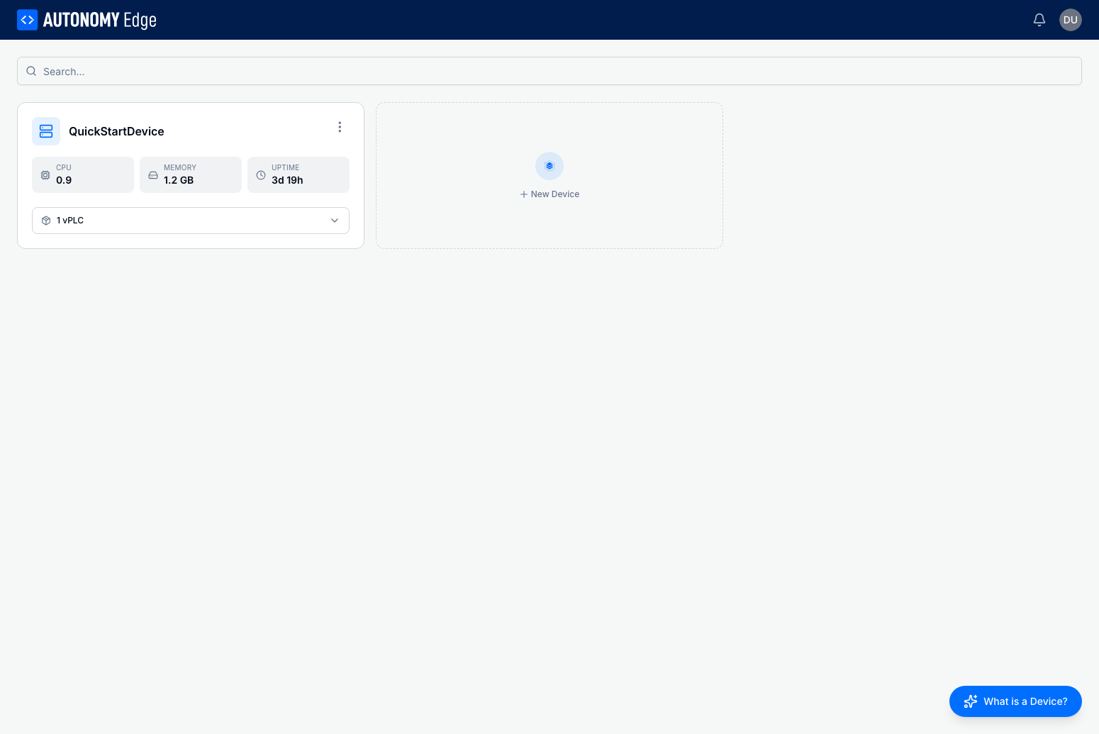
Step 2: Create a vPLC
A vPLC (virtual PLC) is a containerized runtime that executes your automation programs. One of the key advantages of Autonomy Edge is the ability to run multiple vPLC instances on a single physical device. Each vPLC runs in complete isolation with real-time execution, and appears on the network with its own IP address as if it were an independent physical PLC. This allows you to maximize hardware utilization, especially on modern multicore PLCs, PACs, and industrial PCs that are often underutilized when running traditional single-threaded PLC runtimes.
- Click on your Device to open its details
- Navigate to the vPLCs tab
- Click Add vPLC
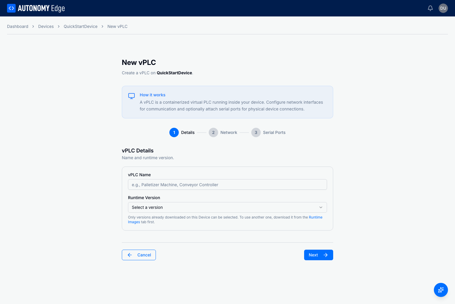
- Enter a vPLC name (e.g., "Demo vPLC")
- Configure the network settings:
- A default virtual NIC (veth0) is created automatically with DHCP
- Click on the NIC to configure static IP if needed
- Click Create to provision the vPLC
The vPLC will start automatically and show a "success" status when ready.
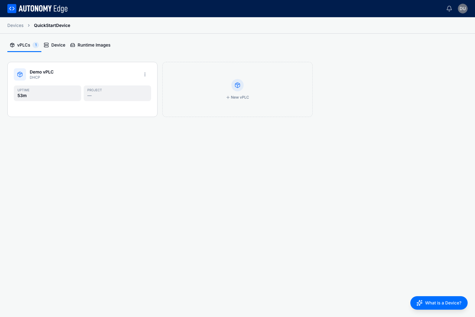
Step 3: Create a New Project
Now let's create a project for our blinking output program.
- Navigate to Projects in the left sidebar
- Click New Project
- Enter a project name (e.g., "BlinkingOutput")
- Select Structured Text as the programming language
- Click Create
The project will open in the OpenPLC Editor IDE.
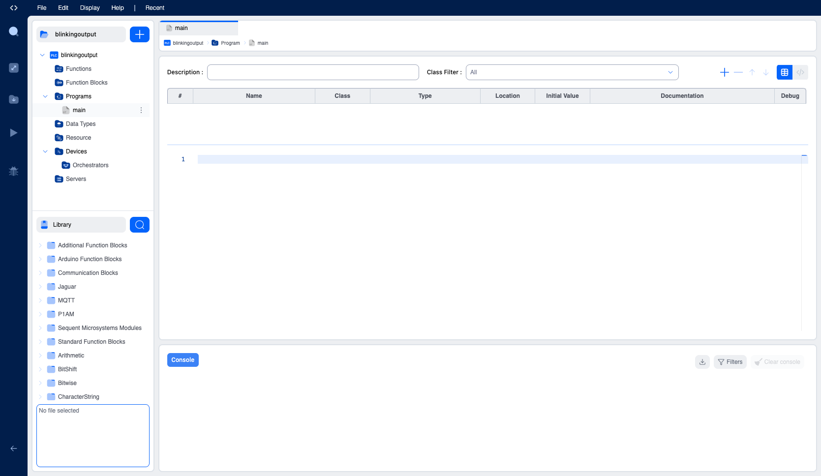
Step 4: Declare Variables
In the IDE, you'll see the variables table at the top and the program editor below. We need two variables:
- A timer to control the blink interval
- An output variable to toggle
Add the Timer Variable
- Click the + button in the variables table toolbar to add a new row
- Set the following values:
- Name:
blink_timer - Class: Local
- Type: TON (search for "TON" in the type dropdown under System)
- Name:
Add the Output Variable
- Click + again to add another variable
- Set the following values:
- Name:
output_state - Class: Local
- Type: BOOL (found under Base Type)
- Location:
%QX0.0
- Name:
The Location field is critical - it maps your program variable to the physical I/O address. The %QX0.0 address corresponds to the first digital output coil, which we'll configure to communicate via Modbus in Step 6.
Understanding Located Variables: In IEC 61131-3, the
%Qprefix indicates an output,Xindicates a bit (boolean), and0.0is the address (byte 0, bit 0). This creates a direct link between your program variable and the Modbus coil address.
Why the class is Local, not Output: The class and the location answer two different questions. The class says who may pass the value in and out of this POU —
InputandOutputdefine the pins of a Function Block, which is why they are not what you want on a Program. The location says which physical address the variable is wired to. A variable driving a real output isLocalwith a%QXlocation; a variable reading a real input isLocalwith a%IXlocation. See Local Variables.
Step 5: Write the Program
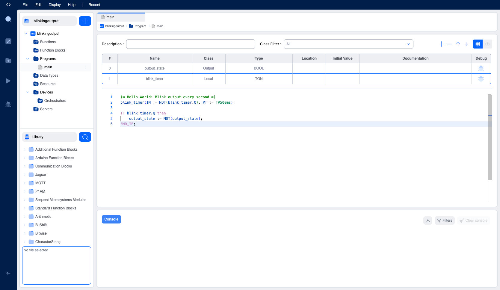
Click in the program editor area (below the variables table) and enter the following Structured Text code:
iecst(* Hello World: Blink output every second *)
blink_timer(IN := NOT(blink_timer.Q), PT := T#500ms);

IF blink_timer.Q THEN
    output_state := NOT(output_state);
END_IF;
This program:
- Uses a TON timer that triggers every 500ms
- Toggles the
output_stateeach time the timer completes - Creates a 1-second blink cycle (500ms on, 500ms off)
Press Cmd+S (Mac) or Ctrl+S (Windows) to save your project.
Step 6: Configure Remote I/O (Modbus)
To connect your program outputs to external devices, we'll configure a Modbus Remote Device.
Add a Remote Device
- Click the blue + button in the left sidebar
- Select Remote Device from the dropdown menu
- Enter a device name (e.g., "ModbusCoils")
- Select Modbus as the protocol
- Click Create
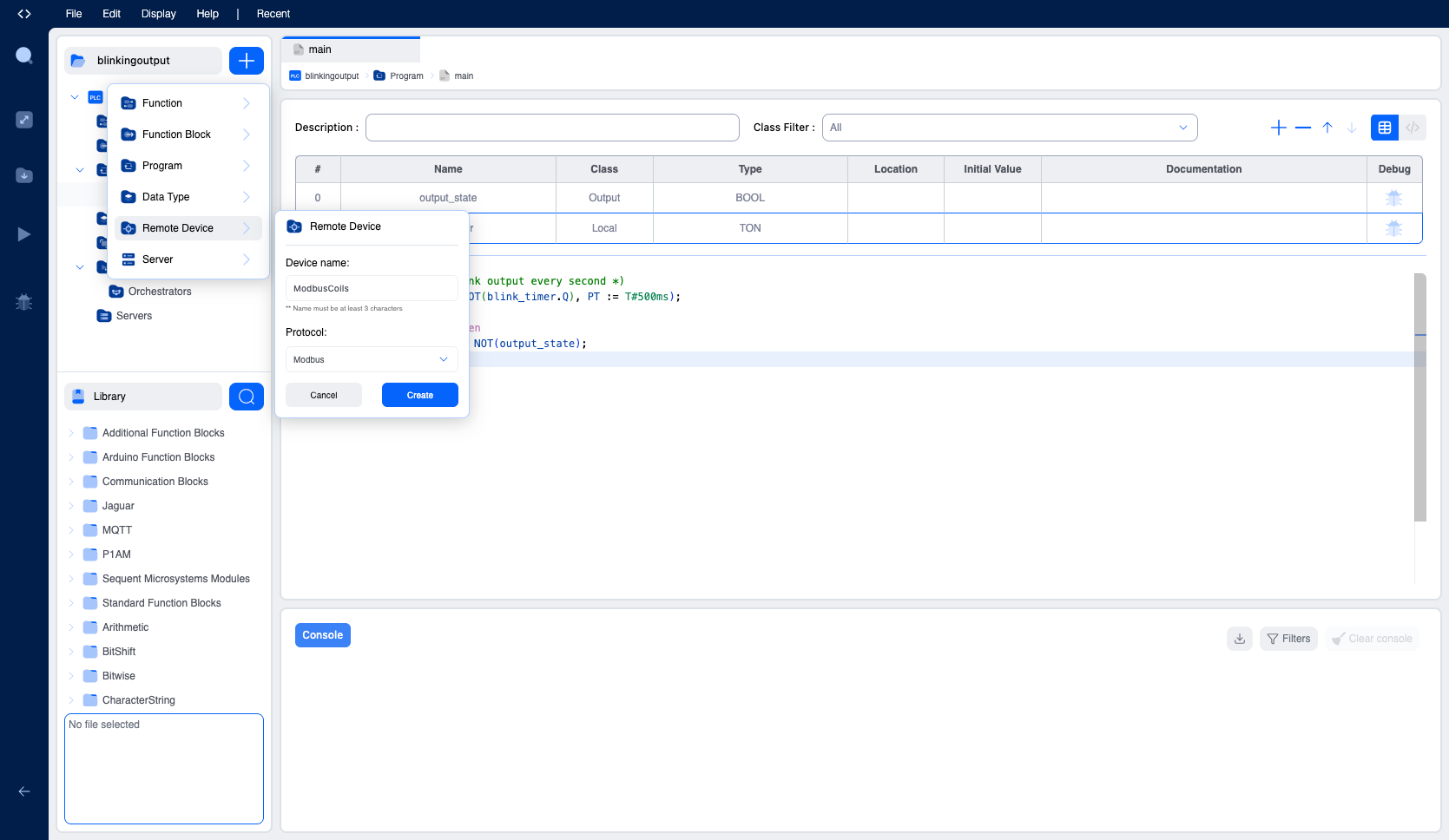
The Remote Device configuration panel will open:
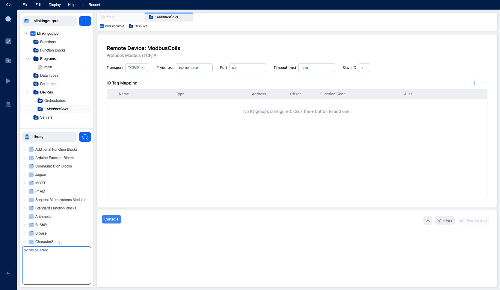
Configure the connection settings:
- Transport: Select TCP/IP for network communication (or RTU for serial)
- IP Address: Enter the IP address of your Modbus slave device (e.g.,
192.168.1.100). The device must be accessible on the same network where the vPLC was configured. - Port: Default is
502(standard Modbus TCP port) - Timeout (ms): Response timeout in milliseconds (default
1000) - Slave ID: The Modbus slave/unit identifier (default
1)
Add an IO Group
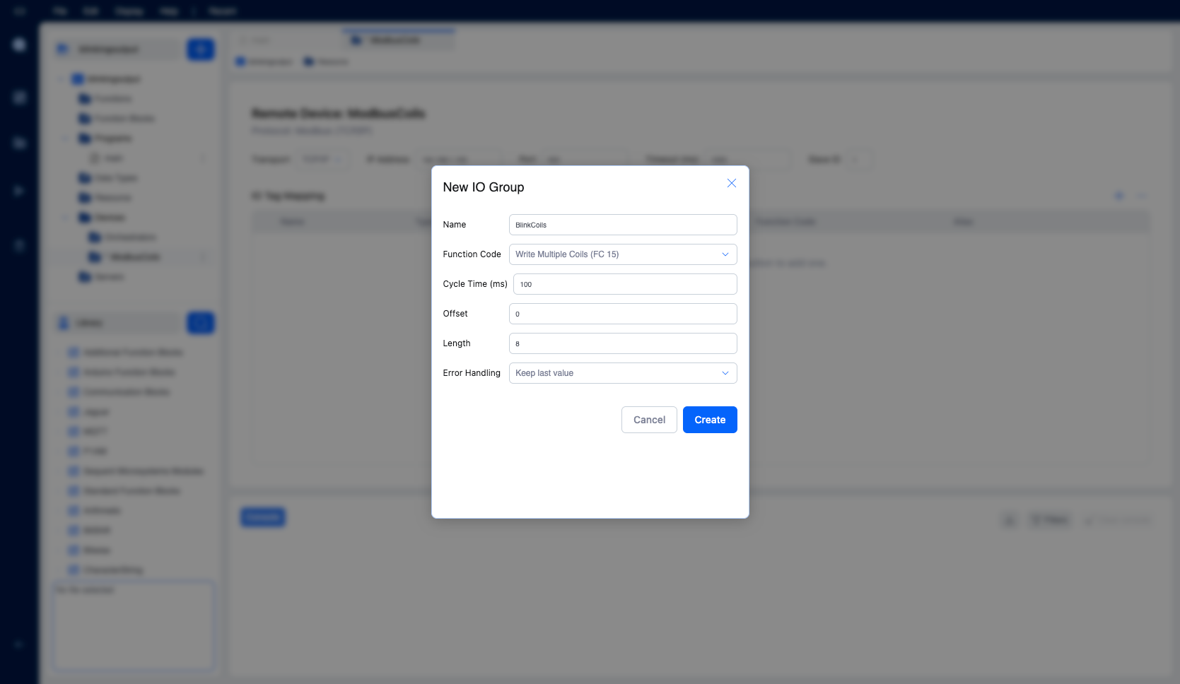
- In the IO Tag Mapping section, click the + button
- Configure the IO Group:
- Name: BlinkCoils
- Function Code: Write Multiple Coils (FC 15)
- Cycle Time (ms): 100
- Offset: 0
- Length: 8
- Error Handling: Keep last value
- Click Create
The IO Group will appear in the table. Click the expand arrow to see individual coil mappings:
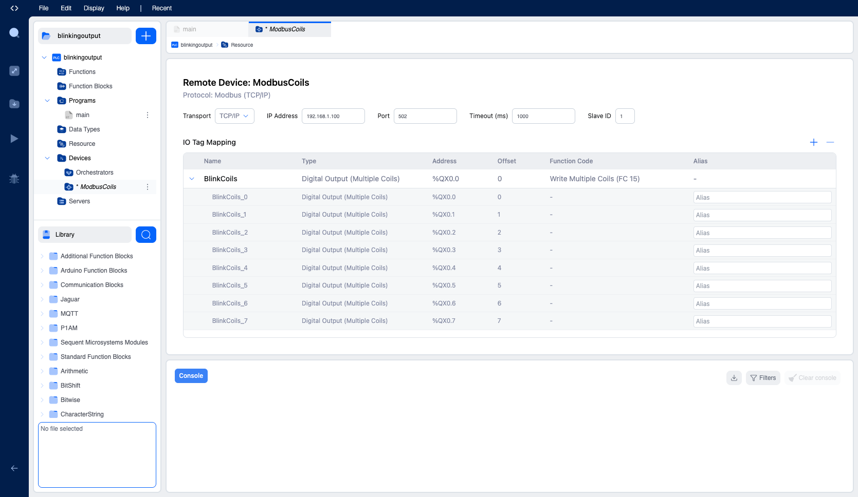
The table shows:
- BlinkCoils (parent): Digital Output (Multiple Coils), Address
%QX0.0, Function Code Write Multiple Coils (FC 15) - BlinkCoils_0 through BlinkCoils_7: Individual coils mapped to
%QX0.0through%QX0.7
This configuration maps 8 digital outputs starting at address %QX0.0 to Modbus coils. Since our output_state variable is located at %QX0.0, it will be automatically written to the Modbus device whenever its value changes.
Step 7: Connect to the vPLC
Now let's connect to the vPLC to deploy your program.
- In the IDE, expand Device in the left sidebar
- Click on Edge Devices to open the Edge Devices panel
- Expand your Device (e.g., "QuickStartDevice") to see your vPLC
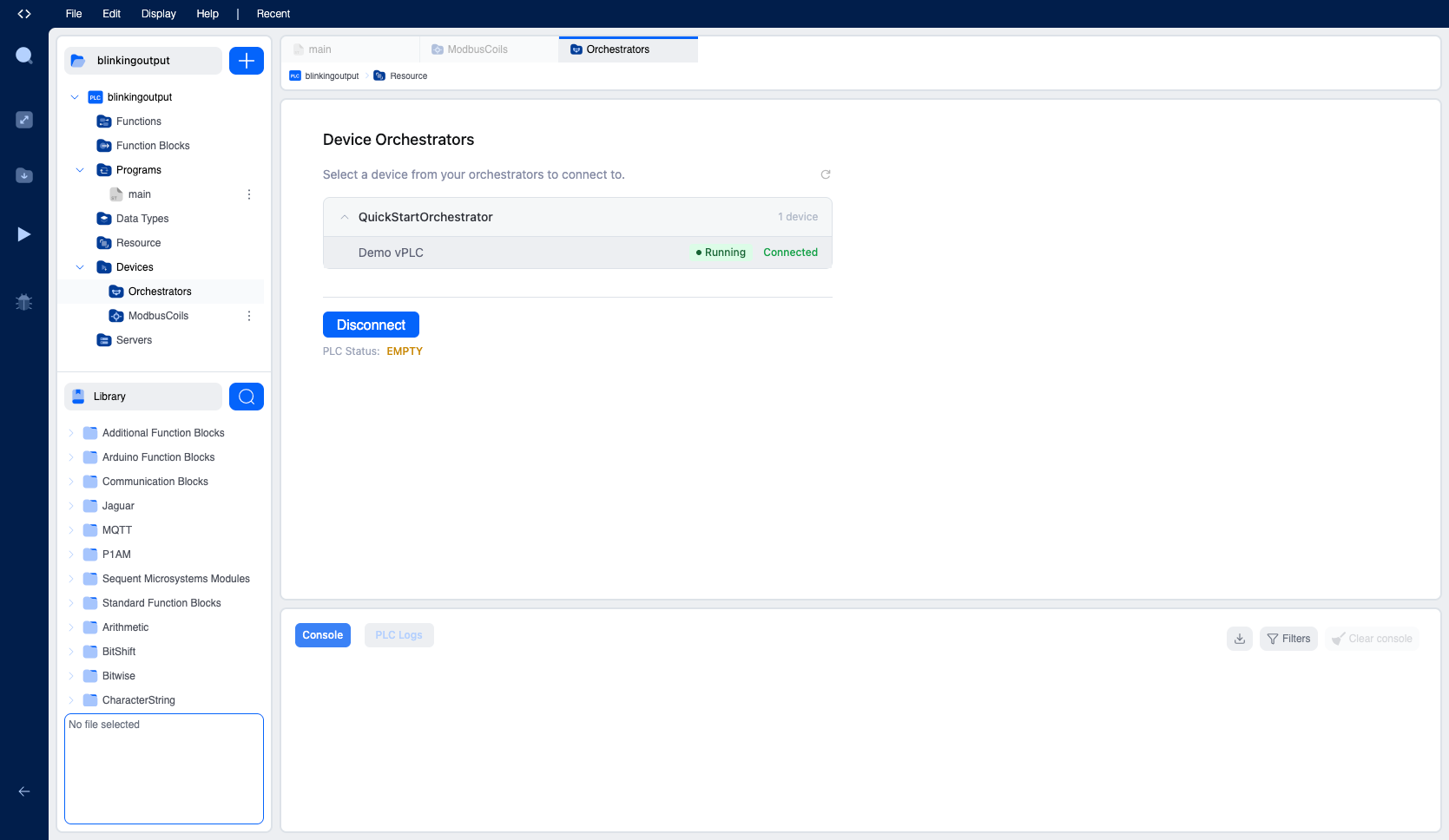
- Click on your vPLC (e.g., "Demo vPLC") to select it (it should show "Running" status)
- Click the Connect button
First-Time User Setup
When connecting to a new vPLC for the first time, you'll need to create an OpenPLC Runtime user account. This account is separate from your Autonomy Edge platform account and is used to authenticate with the PLC runtime.
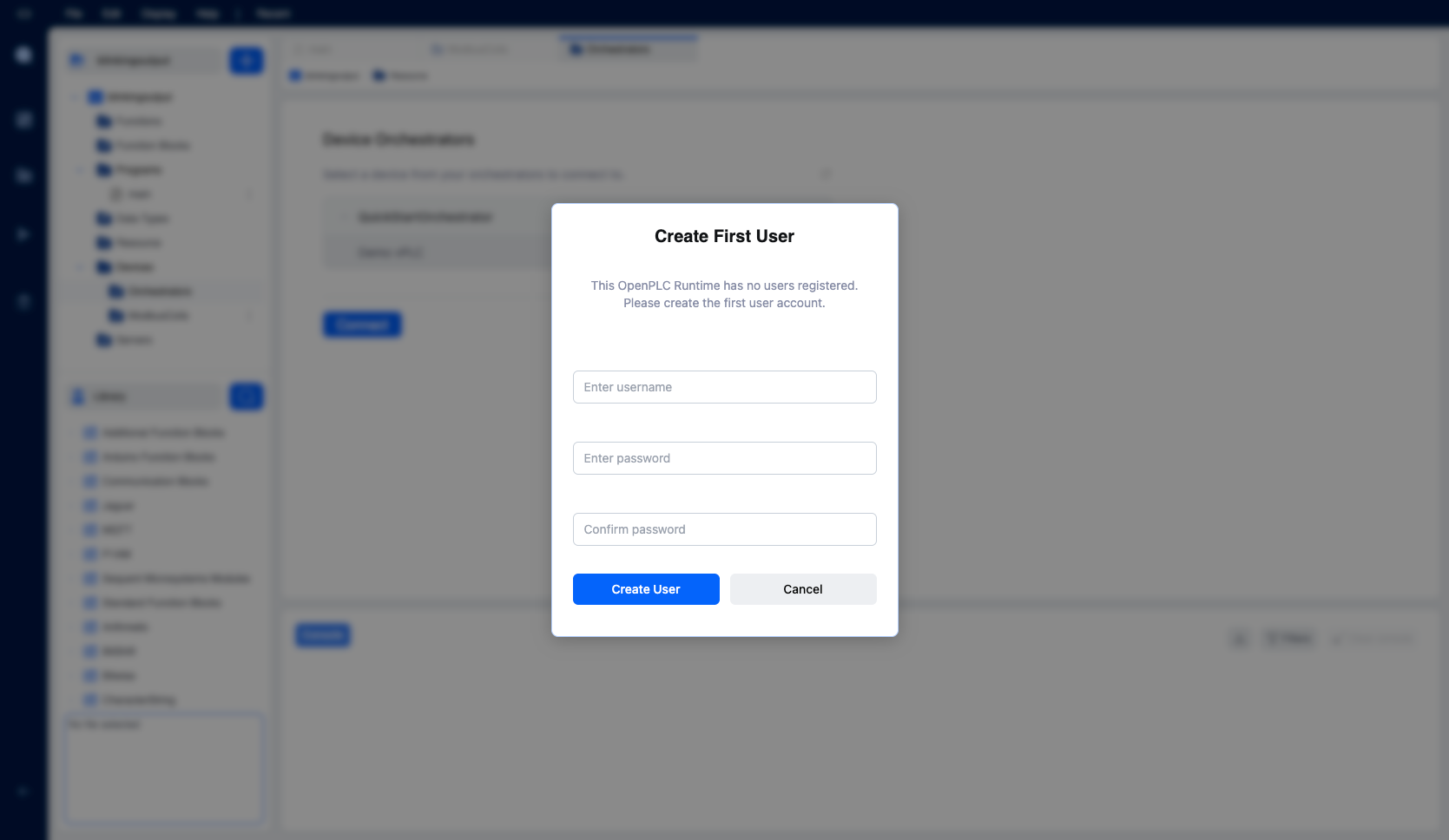
- The Create First User dialog will appear
- Enter a username (e.g., "admin")
- Enter a password and confirm it
- Click Create User
Note: If users have already been created on this vPLC, you'll see a login dialog instead. Enter your OpenPLC Runtime credentials to connect.
Once connected, the vPLC status will show both "Running" and "Connected", and the PLC Status will show "EMPTY" (no program loaded yet).
Step 8: Compile and Deploy
After connecting to the vPLC:
- Click the Download button in the left sidebar (folder icon with a down arrow) to compile and deploy your program
- Check the Console panel at the bottom for compilation progress
- If compilation succeeds, the program will be uploaded automatically
- The PLC Status will change to "RUNNING" when the program is active
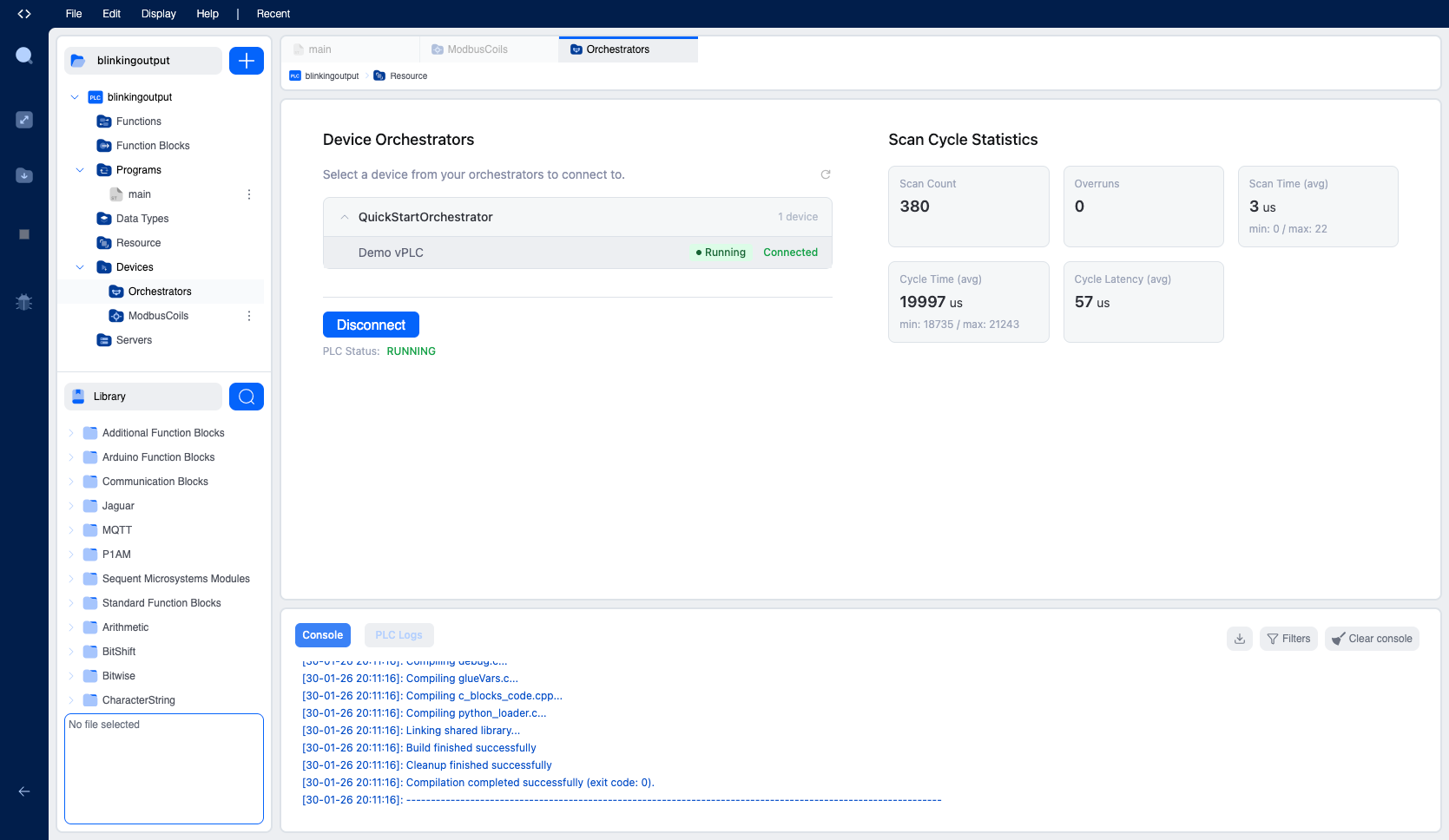
The Scan Cycle Statistics panel shows real-time performance metrics:
- Scan Count: Number of program cycles executed
- Overruns: Cycles that exceeded the target time (should be 0)
- Scan Time (avg): Average execution time per cycle
- Cycle Time (avg): Time between scan starts
- Cycle Latency (avg): Scheduling delay
Verifying Your Program
Once deployed, your blinking output program is running on the vPLC. You can verify this by:
- Watching the Scan Count increment in the Scan Cycle Statistics
- Check the output coils of your Modbus slave device
- Checking the PLC Logs tab for runtime messages
Next Steps
Now that you understand the basics, explore these topics to build more sophisticated automation systems:
Expand Your Programming Skills
- Programming Languages - Learn Ladder Diagram for discrete logic or Function Block Diagram for process control
- Standard Function Blocks - Master timers (TON, TOF, TP), counters (CTU, CTD), and edge detection (R_TRIG, F_TRIG)
- Custom Languages - Extend your PLCs with Python or C++ function blocks
Connect to Real Devices
- Communication Protocols - Configure Modbus servers, clients, and OPC-UA for device integration
- Hardware Configuration - Map program variables to physical I/O pins on supported boards
Scale Your Deployment
- Devices - Deploy Devices to edge machines across multiple sites
- vPLCs - Run multiple vPLCs on a single edge device for workload consolidation
Troubleshooting
vPLC shows "Stopped" status
- Check that your Device is connected (green status indicator)
- Verify network connectivity between the Device and the platform
- Check the Device Agent logs for error messages
Compilation errors
- Ensure all variables are declared before use
- Check for syntax errors in your Structured Text code
- Verify that function block types (like TON) are spelled correctly
Cannot connect to vPLC
- Ensure the vPLC is in "Running" status
- Check that your project is saved before attempting to connect
- Try refreshing the Edge Devices panel (click the refresh icon)
Device ID expired
- Run the installation command again on your Linux device
- A new ID will be generated that you can paste into the Link step
For more help, visit the Troubleshooting section or contact support.
On This Page